General Update
Well I have definitely fallen down on updating the blog. It's been a long time since the last post, but frankly I haven't had very much time for tinkering. Things have been crazy with my upcoming wedding (in just about 2 weeks now), and I've just been busy with I don't know what.
I have been playing around with a few things. I looked into HDMI-CEC interfacing, which I did a lot research on, but don't have really enough coherent information for a blog post. It's even a little too technical for this blog. I'd basically be restating the standard, which is freely available for those interested.
I've also, in the same area, been looking at making a HTPC, but only for ripped DVD's. I worry about the DVD's getting scratched and misplaced. It has happened more than once; believe me. So the solution is to rip them all to a hard drive and play them from a HTPC. I'm leaning away from MythTV, the de facto standard, because I really don't have an interest in the DVR capabilities. MythTV is almost exclusively a DVR with music, DVDs, etc as afterthoughts. I'm considering, instead, XBMC, which is exclusively DVD/Blu-ray/saved video focused. That might make it on the blog eventually.
But to the subject at hand... I have just fixed my car engine of an overheating problem.
Background
Just the other day on the way back to work from a site, I noticed that my car was running a little hot. Now this has been kind of an intermittent problem, and I believe that it is the main reason that I apparently blew a front seal on my A/C compressor towards the end of the summer (the condenser fan is apparently not working). I didn't think too much of it, but I did make a mental note to pay more attention in the future to the temperature.
Then on the way home, I got caught up in fighting traffic and neglected to pay strict attention to the temperature. When I looked down after a minute or two, I saw the gauge was all the way up! I immediately pulled over and turned off the engine.
I opened the hood, turned the key to ON to let the fan run, and turned my heat on full blast. All of these things will let the engine cool faster. Incidentally, after thinking about it I'm not sure that it really matters whether the engine stays hot as long as it's not running. But better safe than sorry.
I made it to the mechanic, who later informed me that he wanted to replace all the hoses, the radiator fan, and the thermostat all for the price of about $800. I'm not sure if I have mentioned this before, but I drive a 1990 Honda Civic that is worth probably about $900, so I was starting to think that old "Cupcake" had finally come to the end if its life. (I didn't name my car, by the way).
As always, I looked into doing the work myself to save money. The parts from Autozone were only about $100 for a fan motor and all the hoses. I didn't think that the thermostat would need replacing. Sure it might be the recommended thing to do (might be), but this is a car that is probably on its last legs anyway. I'm looking to fix it on the cheap.
Replacing the Radiator Upper Hose
I had noticed that the upper hose seemed to be spraying fluid from a small hole near the hose clamp, so I first set about replacing it. I never claim to do everything perfectly the first time, and I made the mistake of disconnecting the hose before draining the system. So the engine drained all of its antifreeze down the engine block and through the car down into my oil change pan. I probably should have thought of that, but whatever. I'm throwing it all away anyway.
Draining the System (as I should have done first)
To drain the system, there is a small plug on the bottom of the radiator accessible from under the car. It's meant to be easy to find. On mine, if you unscrew it a little, then a small hole is exposed, and if you continue the whole thing will come out. You need somewhere for air to come in the system, so make sure you remove the radiator cap. Also turn the A/C to full heat to open the valve to the heater core. Mine is actually a valve connected via a cable to the control knob, but it's old as crap...so yours may be different.
To remove the cap, turn about a quarter turn counter-clockwise. Of course the engine should be nice and cool when you do this, so you don't spray hot antifreeze all over yourself. To remove the cap all the way, push down and continue to turn counter-clockwise. Then it should pop right off.
On my car there is also an air vent up near where the upper radiator hose connects to the engine. You'll need this open to fill it later anyway, so you might as well do it now.
Changing the Hose (in the right order)
The upper hose is ridiculously easy to change. First you loosen the hose clamps with a screwdriver. No problem there. Then give the hose a good prolonged pull with a little twisting and working back and forth. It should pop right off. You might be able to spray a little WD-40 around the end to try to loosen it up a bit. I'm not sure if that helped me or not.
After the hose is off, just grab the new one, put the hose clamps on it loosely, shove it on the barbs, and clamp it down. Make sure you clamp after the little lip on the barb. No problem.
Refilling the System
I followed the directions in my shop manual pretty closely. I managed to find it on usenet a long time ago and downloaded it. You should have taken off the cap for the draining, so you just need to replace the plug in the bottom and start filling the system with a funnel. Leave the vent by the engine open until antifreeze steadily starts flowing out. This happened in about the last 2 inches of filling for me. You need to tighten it back down and then fill the radiator to the bottom of the neck with antifreeze. Leave the cap off for now.
Also fill the reservoir to the max line with antifreeze. I found that shining a flashlight down into the reservoir will make the antifreeze glow a little through the plastic so that you can see the level easily.
Burping the System
Because we just filled an empty system with fluid, there are some pockets of air in there. If we put the cap on, there wouldn't be a very good place for the air to go, so we leave the cap off and start the car. Let the car run for a good long while to warm up. When the car is first started, all of the coolant just loops around the engine as it warms up. It doesn't even go through the radiator. As the coolant begins to warm up with the engine, more is passed through the radiator to begin to take heat away from the engine. Also, the heated liquid will expand and fill in all the space. So you want to make sure that the car gets nice and warm for the purpose of getting all the air out.
In my case, quite a bit of antifreeze bubbled out of the open cap from time to time. I just wrapped it with a shop towel and soaked it up as much as possible. At first I imagine that this is because the air is pushing the fluid out as it works it way out of the system. Later, the fluid is actually expanding and contracting due to the temperature changes. At least that's my theory.
My manual said to wait until the fan comes on at least twice before replacing the cap.
Drive Around
After replacing the hose and coolant, I did some driving. To my delight I couldn't get the thing to overheat. I was very excited, and I thought that I had fixed the whole thing for $20. Luckily this proved to not be too far from the truth.
Check for Leaks
Here's where I saw my mistake. I had done fine with the hose I replaced, but it actually wasn't even leaking. The upper heater core hose was spraying from nearby, and it looked like the stream was coming from the radiator hose. It seemed that leaving the system in this state would put me right back where I had started in the near future, so I went back out to Autozone and purchased the heater hose (and returned the fan motor). Another $10.
Changing the Heater Hose
The heater hose is as difficult to change as the upper radiator hose was easy. It's tucked way the heck under a bunch of crap. The spark plug wires get in the way. I felt like I was going to break the heater valve. And to top it all off, it has those infernal spring clips on it instead of worm clamps. The only advice I can give you is that there is an easiest angle to get at those clamps. For me, I ended up hugging the engine so that I couldn't even see the clamp. I put the pliers on by feel with my other hand. Actually I do have two other tricks for those things. First try to grab them with your pliers parallel to the plane of the ring. That seems to be the easiest way. Secondly, once you have them squeezed, don't try to move them with the pliers. Use your other hand to gently push them down the hose while maintaining pressure on the pliers. Otherwise you'll end up cursing, sweating, and shaking from holding the same leaning position for so long (like me). Once the damned clamps are figured out, it's not too hard to change the hose. Just keep at it, and try to stay patient.
Finishing Up
I actually had to drain the system a second time to replace the second hose, but I was able to save all the fluid to put back in. After driving around some more and making sure the clamps were all secure, I have decided that the car is fixed. The temperature is rock solid where it normally is, and I am very happy. I was definitely able to see the little hole in the old heater hose that was causing all the problems.
In retrospect, I believe that my whole problem was that I was low on coolant. The heater hose had been leaking for a while, and I had thought that it was transmission fluid from another previous leaking hose. But actually, I've been losing coolant for a while now. I guess it finally got so low that the system couldn't keep the engine cool in traffic.
Also, I have no idea how old that coolant was. It was pretty nasty looking when compared to the new clean stuff. I have read that you can flush the system with water in between draining and filling. Just pump it full of water and drive it or run it for a while. Then drain it and put the real stuff in.
So for the grand total of $40, I have fixed my car's cooling problem. $20 in antifreeze and two $10 hoses. If I'd known exactly what to do, I could have done it for $20, but I'm not too worried about that when the alternative was $800, or more realistically a new car.
If someone has a similar problem, I hope that they see that it might be very simple to fix. Don't let the mechanic talk you into changing every freaking thing in your car just because one hose has a leak and you're low on coolant.
Thanks for reading,
Bill
Friday, December 3, 2010
Wednesday, August 11, 2010
Guitar Tone Circuit Analysis Part 3
Introduction
Well I had a very impressive bit of research put together based on adding a parallel resistor to linearize my 1-pole tone circuit from Part 2. I was putting together the post when I realized that the resistance was almost exactly the same as a log pot alone. But the plot looked so different from the one I had posted before! What was going on?
I eventually realized that the plot I put up for the 1-pole circuit was by far the wrong plot. The information is accurate, but I shouldn't have plotted Cutoff Frequency vs. Resistance for a log pot! That gives us no indication of how the log pot will perform in comparison to a linear pot. What I should have graphed was cutoff frequency vs. wiper position. This is the plot that follows.
 As you can see, it's much prettier. Oddly enough, the Sallen-Key plot seems to be pretty unaffected by the change. Not sure why, but I'm tired of looking at it now.
The result of my research tonight is that you can put a 100 ohm resistor in parallel with the top half of the pot and achieve essentially the same result. That should have been pretty obvious in the first place. I will re-examine whether anything is actually gained from that configuration at a later date and possibly post back.
*** Update ***
I've looked again, and the benefit of using a parallel resistor is completely non-existent. On the bright side, I've figured out how to flatten out the curve more at the expense of loosing out on the lowest frequency possible.
 I've run the numbers for all pots currently offered at Futurlec. By the way, Futurlec is amazing! I've used them before, but I thought I'd give them some props for having ridiculous prices and a surprisingly good and growing pot selection. It's the only place I've seen with anti-log pots. They are all mini-pots, but that's not too big a deal.
Based on the plot above, I think I'll be going with a 20K for the tone pot (dual ganged). I'll have to figure out this triple pot for the volume later. Right now I'm working on the prototype. Back to having everything breadboarded and alligator clipped into the amp.
Thanks for reading,
Bill
Well I had a very impressive bit of research put together based on adding a parallel resistor to linearize my 1-pole tone circuit from Part 2. I was putting together the post when I realized that the resistance was almost exactly the same as a log pot alone. But the plot looked so different from the one I had posted before! What was going on?
I eventually realized that the plot I put up for the 1-pole circuit was by far the wrong plot. The information is accurate, but I shouldn't have plotted Cutoff Frequency vs. Resistance for a log pot! That gives us no indication of how the log pot will perform in comparison to a linear pot. What I should have graphed was cutoff frequency vs. wiper position. This is the plot that follows.

The result of my research tonight is that you can put a 100 ohm resistor in parallel with the top half of the pot and achieve essentially the same result. That should have been pretty obvious in the first place. I will re-examine whether anything is actually gained from that configuration at a later date and possibly post back.
*** Update ***
I've looked again, and the benefit of using a parallel resistor is completely non-existent. On the bright side, I've figured out how to flatten out the curve more at the expense of loosing out on the lowest frequency possible.

Based on the plot above, I think I'll be going with a 20K for the tone pot (dual ganged). I'll have to figure out this triple pot for the volume later. Right now I'm working on the prototype. Back to having everything breadboarded and alligator clipped into the amp.
Thanks for reading,
Bill
Friday, July 30, 2010
Making an Optimal Log Pot
Introduction
After taking a look at the famed "The Secrete Life of Pots" again, I realized that it might be useful for me to make my own blend pot. I have discovered that the blend pot I have unfortunately does not cross the streams the way it should. At the center detent, both pots are at full volume. Deviating in either direction lowers the volume of one of the pots. So this means that I will be much louder in the middle than at either of the extremes, which is undesirable.
The author mentions that it is possible to get arbitrarily close to a logarithmic pot, so I decided to bust out Matlab and see if that was true.
Method
First I verified that the calculations were indeed correct. Actually I found a small typo in them. He uses two different definitions of the b variable that are reciprocals of each other. On the graph, the numbers say "b=0,1,2,3,4,5,6" when, going by the previous calculations, "b=1/0, 1/1, 1/2, 1/3, 1/4, 1/6" to produce the graph shown. The actual equations were correct, both the resistor-based and the ratio-based.
Secondly, what should a log pot actually look like? Incidentally, the plot is actually an exponential 10^x graph. The plot will look like a line on a semi-log plot. But which part of this plot should we choose? Each section looks different, and wider range will have a different curve than a smaller one. After reading the Wikipedia article on sound pressure, I decided to pick the range from 0-60db (10^(0...60/20) as my target range. This represents the range from silent to coming close to hearing damage. And that's what we want right? :)
After that, I used the "fminunc" (for function minimize unconstrained) function in Matlab to minimize the difference between the chosen log plot and the attempt to copy it. The independent variable was b.
Results
It is not quite true that you can get arbitrarily close to the log pot, at least not with this choice for the log pot curve. I used two methods for the error calculation: least sum of absolute value and least sum of squares. Here are the results.


Running the minimization on both methods produced values of
b = 0.0574 for the least sum of absolute value of errors
b = 0.0709 for the least sum of squared errors
So the resistor at the wiper should be 5.74% or 7.09% of the total resistance of the pot, depending on which method of optimisation you choose.
Here are the plots for those values.

Conclusion
As you can see, the plots are fairly close, but by no means perfect. To the ear, you probably couldn't tell very much difference.
As mentioned in TSLoP, using this method severely drops the resistance of the load to the pickup. Also it changes the resistance depending on wiper position. So you probably would want to put an opamp buffer or something in between the pickup and the fake log pot.
The drop in resistance is by a factor of 0.0543 for the ABS result and 0.0662 for the LSQ result in the worst position (1/(1+1/b) from TSLoP). The worst position is full volume, since there will be no top resistor in series with the parallel pair. So we're talking about turning a 500K pot into 27K or 33K at the worst wiper position. Still easily drive from an opamp, but pretty nasty for a pickup.
I'm considering adding a couple of opamps to the circuit so that I can take a dual-ganged linear pot and turn it into a dual log pot where one is the opposite of the other. That's hard to explain. Just look at the graph.

That way the volume should remain pretty constant as you sweep from one side to the other.

Now if only I could find one with a center detent...
Code used for calculating follows...
Thanks for reading,
Bill
After taking a look at the famed "The Secrete Life of Pots" again, I realized that it might be useful for me to make my own blend pot. I have discovered that the blend pot I have unfortunately does not cross the streams the way it should. At the center detent, both pots are at full volume. Deviating in either direction lowers the volume of one of the pots. So this means that I will be much louder in the middle than at either of the extremes, which is undesirable.
The author mentions that it is possible to get arbitrarily close to a logarithmic pot, so I decided to bust out Matlab and see if that was true.
Method
First I verified that the calculations were indeed correct. Actually I found a small typo in them. He uses two different definitions of the b variable that are reciprocals of each other. On the graph, the numbers say "b=0,1,2,3,4,5,6" when, going by the previous calculations, "b=1/0, 1/1, 1/2, 1/3, 1/4, 1/6" to produce the graph shown. The actual equations were correct, both the resistor-based and the ratio-based.
Secondly, what should a log pot actually look like? Incidentally, the plot is actually an exponential 10^x graph. The plot will look like a line on a semi-log plot. But which part of this plot should we choose? Each section looks different, and wider range will have a different curve than a smaller one. After reading the Wikipedia article on sound pressure, I decided to pick the range from 0-60db (10^(0...60/20) as my target range. This represents the range from silent to coming close to hearing damage. And that's what we want right? :)
After that, I used the "fminunc" (for function minimize unconstrained) function in Matlab to minimize the difference between the chosen log plot and the attempt to copy it. The independent variable was b.
Results
It is not quite true that you can get arbitrarily close to the log pot, at least not with this choice for the log pot curve. I used two methods for the error calculation: least sum of absolute value and least sum of squares. Here are the results.


Running the minimization on both methods produced values of
b = 0.0574 for the least sum of absolute value of errors
b = 0.0709 for the least sum of squared errors
So the resistor at the wiper should be 5.74% or 7.09% of the total resistance of the pot, depending on which method of optimisation you choose.
Here are the plots for those values.

Conclusion
As you can see, the plots are fairly close, but by no means perfect. To the ear, you probably couldn't tell very much difference.
As mentioned in TSLoP, using this method severely drops the resistance of the load to the pickup. Also it changes the resistance depending on wiper position. So you probably would want to put an opamp buffer or something in between the pickup and the fake log pot.
The drop in resistance is by a factor of 0.0543 for the ABS result and 0.0662 for the LSQ result in the worst position (1/(1+1/b) from TSLoP). The worst position is full volume, since there will be no top resistor in series with the parallel pair. So we're talking about turning a 500K pot into 27K or 33K at the worst wiper position. Still easily drive from an opamp, but pretty nasty for a pickup.
I'm considering adding a couple of opamps to the circuit so that I can take a dual-ganged linear pot and turn it into a dual log pot where one is the opposite of the other. That's hard to explain. Just look at the graph.

That way the volume should remain pretty constant as you sweep from one side to the other.

Now if only I could find one with a center detent...
Code used for calculating follows...
function G = logpot(b)
% logpot accepts one row matrix "b" that contains
% all values of "b" for which a dataset should be generated
% It returns the "ideal log gain" followed by the generated
% datasets for the b values provided.

% setup pot position values
a = repmat(linspace(0,1,50)', size(b), 1);

% replicate b to match a's height
b = repmat(b, 50, 1);

% do the math
G = 1./ ((ones(size(a))-a)./a + (ones(size(a))-a)./b + ones(size(b)));

% create our "ideal log gain" (0-60dB)
glog = logspace(0,60/20,50);
glog = glog ./ max(glog);

% concatenate "ideal log gain" with the generated datasets
G = [ glog' G ];


----------------------------------------
The command to do the optimisation is

fminunc(@myfun, 1/6)

This is the function used in the optimisation to calculate total error.

function f = myfun(b)
% function is
%           1
%---------------------
%  _1-a_ + _1-a_ +  1
%    b       a

% precalculated to make things faster.
% a = linspace(0,1,50);
% a1 = 1-a
% a2 = (1-a)/a
a1 =[ 1.0000    0.9796    0.9592    0.9388    0.9184    0.8980    0.8776    0.8571    0.8367    0.8163    0.7959    0.7755    0.7551    0.7347    0.7143    0.6939    0.6735    0.6531    0.6327    0.6122    0.5918    0.5714    0.5510    0.5306    0.5102    0.4898    0.4694    0.4490    0.4286    0.4082    0.3878    0.3673    0.3469    0.3265    0.3061    0.2857    0.2653    0.2449    0.2245    0.2041    0.1837    0.1633    0.1429    0.1224    0.1020    0.0816    0.0612    0.0408    0.0204         0 ];
a2 =[ Inf   49.0004   24.5004   16.3337   12.2504    9.8004    8.1671    6.9997    6.1248    5.4443    4.8999 4.4545    4.0833    3.7693    3.5001    3.2667    3.0626    2.8825    2.7224    2.5788    2.4499    2.3333    2.2272    2.1304    2.0417    1.9600    1.8846    1.8149    1.7500    1.6897    1.6334    1.5806    1.5312    1.4848    1.4411    1.4000    1.3611    1.3243    1.2895    1.2564    1.2250    1.1952    1.1667    1.1395    1.1136    1.0889    1.0652    1.0425    1.0208    1.0000 ];

% glog is a 0-60 db curve normalized to 0-1
% glog = logspace(0,60/20,50); glog = glog ./ max(glog)
glog =[ 0.0010    0.0012    0.0013    0.0015    0.0018    0.0020    0.0023    0.0027    0.0031    0.0036    0.0041    0.0047    0.0054    0.0063    0.0072    0.0083    0.0095    0.0110    0.0126    0.0146    0.0168    0.0193    0.0222    0.0256    0.0295    0.0339    0.0391    0.0450    0.0518    0.0596    0.0687    0.0791    0.0910    0.1048    0.1207    0.1389    0.1600    0.1842    0.2121    0.2442    0.2812    0.3237    0.3728    0.4292    0.4942    0.5690    0.6551    0.7543    0.8685    1.0000 ];

%f = 1./ ( a1./b + a2 );
f1 = 1./ ( a1./b + a2 )  - glog;

f = sum(abs(f1));
%f = sum(f1.^2);


----------------------------------------

This is the code I used to generate the main results graph

plot(100*linspace(0,1,50)', 100*logpot([0.0574 0.0709]));
xlabel('Wiper Position (%)');
ylabel('Gain (%)');
legend('Real Log 0-60 dB', 'Simulated b=0.0574 (Least ABS)', 'Simulated b=0.0709 (Least Squares)', 'Location', 'NorthWest');
title('Simulated Log Pots');
Thanks for reading,
Bill
Sunday, July 18, 2010
Wiring Started on Guitar!
Well after being extremely busy with work, and taking on a couple of other projects, I am finally getting back to the guitar. It's been sitting in pieces in my room for over a month now.
Today the guitar finally has reclaimed its original shape! I've wired the original pickups back into the guitar with the Series/Parallel/Coil Cut switch in place. The result is a 3 wire + shield output that has signal ground, neck out, bridge out, and shield. Soon I will make a prototype of the active circuit on the breadboard again. I started it a while back but didn't finish it.
Unfortunately, the sound is still limited by the pickups themselves. I will have to go for a higher quality pickup (like the Seymour Duncan Seth Lover SH-55's mentioned before) before I get a really great sound. That being said, I do hear a substantial difference from before.
Right now, the wires are plugged straight into the amp itself, so the impedance presented to the pickups is probably on the order of 1M. The highs are coming out nicely in all modes. The neck pickup sounds great, but the bridge is a little harsh.
Switching between Series, Parallel, and Coil Cut produces a noticable difference in tone. I am very happy to have the guitar in a playable state again. I will post pictures and the new schematics later.
Thanks for reading,
Bill
Tuesday, June 8, 2010
Guitar Tone Circuit Analysis Part 2
Introduction
After the previous post analyzing traditional guitar circuits, I have done more research on something that would be better. I have come up with two exciting circuits. Well I guess they're only exciting if you get excited about such things. Both allow direct maniupulation of the cutoff frequency of the circuit without a change in gain, and both are active.
1 Pole Circuit
The first circuit is a standard 1 pole active filter. It uses an opamp, a capacitor, and two equal resistors for unity gain. Actually, the gain is -1 (not dB mind you), so it's an inverting amplifier. But we don't care too much about that.
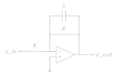 The circuit is a variation on a standard opamp inverter, except now there is a capacitor in parallel with the feedback resistor. So higher frequencies get a lower feedback resistance, which decreases their gain. The equation for the magnitude of the gain in this circuit is as follows.

The cutoff frequency is the same as the passive 1 pole low pass filter.
 So we can manipulate the cutoff frequency directly by adjusting R and keeping C constant. The values I chose were
Rtone = 100 Ohms
TonePot = 50KOhms
C = 0.22uF
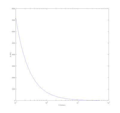
Rtone is put in series with both pots. So R = Rtone + Rtonepot. This gives us a stop at the high end of fc as seen on the graph. The range is 7.2Khz to 14 Hz. 7.2 Khz is very high to listen to alone. I will have to decide whether I like it as a maximum for the circuit. The idea is to crank the tone circuit all the way up and hardly affect the tone at all. So everything under 7.2Khz will be left untouched, and the response will start to drop off after that. But in all seriousness, the pickup itself probably will attenuate those frequencies quite a bit anyway.
 **********
Note: This plot is not the correct graph. See Part 3 for a useful graph.
**********
There are two drawbacks to this circuit. Firstly, the frequency change is not linear with change in R. In fact, you'll notice that it is not even linear with changes in log(R). But it doesn't look too terrible with a log tone pot. And hey, we're going from no control to some control, so how upset can we be about nonlinearities. Secondly, it requires a dual-ganged pot. Both resistors much change by the same amount, or the overall magnitude of the gain will change as well. Basically, the inverting amplifier will begin to amplify or attenuate the signal. We only want that to happen when we adjust the volume pot. So there's no way around the problem.
2 Pole Circuit
The second circuit is a Butterworth filter implementation in a Sallen-Key topology. Here is the schematic.
 I was pretty happy about the math on this one, so I'll give a little bit more detail. The general gain for the Sallen-Key topology is...

Where Z1 = R1, Z2 = R2, Z3 = 1/(C2s), Z4 = 1/(C1s)
The cutoff frequency and Q factor are given as follows.


We set Q = 1/sqrt(2) to achieve a Butterworth filter. This filter has a maximally flat frequency response prior to the cutoff frequency. Because this is a 2 pole filter, it drops off more steeply than the 1 pole filter described before. With the added steepness, which is desireable in many applications, comes the chance for a non-flat response in the "passband" (prior to the cutoff frequency). The filters tend to have a high peak near the cutoff frequency before dropping off. Designing Q = 1/sqrt(2) makes this peak disappear.
Lets set the resistances equal to each other so that we can use a dual-ganged pot and see what falls out of the equations.

When we plug this back into the Q equation, look what falls out...

That's great! We can totally eliminate the resonate peak around the cutoff frequency by making one capacitor double the other. And this holds true for all values of R, so the filter's response will not change as we adjust the cutoff frequcy. Now, how will that frequency be affected by changing the resistors now that we've come up with the above equations? Substituting in to the fc equation, we get...

That's the exciting part. I hope you're as excited as I am. The equation is almost exactly like the one we had for the 1 pole filter! The factor of sqrt(2) will tend to make our cutoff frequencies a little smaller, but it's a constant factor. Everything remains controllable from a single dual-ganged pot.
Choosing
Rtone = 1 KOhms
Rtonepot = 50 KOhms
C1 = 0.02uF
C2 = 0.01uF
We get the following plot for cutoff frequency.
 As you can see, our cutoff frequency on the low end of the R range is higher, and we probably don't go quite as low when we max it out. Actually, for these values the lowest frequency is 220Hz, which is a little high. But different values will yield a better range.
Conclusion
I have shown two circuits with fully adjustable cutoff frequencies. The only drawbacks are the need for a power supply and the dual-ganged pot that will have to be added. For my own purposes, I am back to trying to make a 3-ganged pot. I should be able to do it, since my friend James offered to machine me some parts if I needed them. He's a nice guy.
I will be using the first circuit (1 pole), because it will be more like the original response of the original tone circuit. I realize that I no longer have the ability to flatten out the gain curve, but was that really even that useful? Now I can just move the cutoff frequency down the line and I won't attenuate anything anyway. In my opinion, these are vastly superior circuits. Still, I choose the 1 pole model, because I worry that the 2 pole would drop off too quickly. Plus the 1 pole is slightly easier to source parts for, due to the need for only 1 capacitor. (Yes you can just put two in parallel to get twice the capacitance).
The circuit is finally coming together. I will post the final schematic whenever I get a chance.
Thanks for reading,
Bill
After the previous post analyzing traditional guitar circuits, I have done more research on something that would be better. I have come up with two exciting circuits. Well I guess they're only exciting if you get excited about such things. Both allow direct maniupulation of the cutoff frequency of the circuit without a change in gain, and both are active.
1 Pole Circuit
The first circuit is a standard 1 pole active filter. It uses an opamp, a capacitor, and two equal resistors for unity gain. Actually, the gain is -1 (not dB mind you), so it's an inverting amplifier. But we don't care too much about that.


The cutoff frequency is the same as the passive 1 pole low pass filter.

Rtone = 100 Ohms
TonePot = 50KOhms
C = 0.22uF
Rtone is put in series with both pots. So R = Rtone + Rtonepot. This gives us a stop at the high end of fc as seen on the graph. The range is 7.2Khz to 14 Hz. 7.2 Khz is very high to listen to alone. I will have to decide whether I like it as a maximum for the circuit. The idea is to crank the tone circuit all the way up and hardly affect the tone at all. So everything under 7.2Khz will be left untouched, and the response will start to drop off after that. But in all seriousness, the pickup itself probably will attenuate those frequencies quite a bit anyway.

Note: This plot is not the correct graph. See Part 3 for a useful graph.
**********
There are two drawbacks to this circuit. Firstly, the frequency change is not linear with change in R. In fact, you'll notice that it is not even linear with changes in log(R). But it doesn't look too terrible with a log tone pot. And hey, we're going from no control to some control, so how upset can we be about nonlinearities. Secondly, it requires a dual-ganged pot. Both resistors much change by the same amount, or the overall magnitude of the gain will change as well. Basically, the inverting amplifier will begin to amplify or attenuate the signal. We only want that to happen when we adjust the volume pot. So there's no way around the problem.
2 Pole Circuit
The second circuit is a Butterworth filter implementation in a Sallen-Key topology. Here is the schematic.


Where Z1 = R1, Z2 = R2, Z3 = 1/(C2s), Z4 = 1/(C1s)
The cutoff frequency and Q factor are given as follows.


We set Q = 1/sqrt(2) to achieve a Butterworth filter. This filter has a maximally flat frequency response prior to the cutoff frequency. Because this is a 2 pole filter, it drops off more steeply than the 1 pole filter described before. With the added steepness, which is desireable in many applications, comes the chance for a non-flat response in the "passband" (prior to the cutoff frequency). The filters tend to have a high peak near the cutoff frequency before dropping off. Designing Q = 1/sqrt(2) makes this peak disappear.
Lets set the resistances equal to each other so that we can use a dual-ganged pot and see what falls out of the equations.
When we plug this back into the Q equation, look what falls out...

That's great! We can totally eliminate the resonate peak around the cutoff frequency by making one capacitor double the other. And this holds true for all values of R, so the filter's response will not change as we adjust the cutoff frequcy. Now, how will that frequency be affected by changing the resistors now that we've come up with the above equations? Substituting in to the fc equation, we get...

That's the exciting part. I hope you're as excited as I am. The equation is almost exactly like the one we had for the 1 pole filter! The factor of sqrt(2) will tend to make our cutoff frequencies a little smaller, but it's a constant factor. Everything remains controllable from a single dual-ganged pot.
Choosing
Rtone = 1 KOhms
Rtonepot = 50 KOhms
C1 = 0.02uF
C2 = 0.01uF
We get the following plot for cutoff frequency.

Conclusion
I have shown two circuits with fully adjustable cutoff frequencies. The only drawbacks are the need for a power supply and the dual-ganged pot that will have to be added. For my own purposes, I am back to trying to make a 3-ganged pot. I should be able to do it, since my friend James offered to machine me some parts if I needed them. He's a nice guy.
I will be using the first circuit (1 pole), because it will be more like the original response of the original tone circuit. I realize that I no longer have the ability to flatten out the gain curve, but was that really even that useful? Now I can just move the cutoff frequency down the line and I won't attenuate anything anyway. In my opinion, these are vastly superior circuits. Still, I choose the 1 pole model, because I worry that the 2 pole would drop off too quickly. Plus the 1 pole is slightly easier to source parts for, due to the need for only 1 capacitor. (Yes you can just put two in parallel to get twice the capacitance).
The circuit is finally coming together. I will post the final schematic whenever I get a chance.
Thanks for reading,
Bill
Thursday, June 3, 2010
Guitar Tone Circuit Analysis
Introduction
In keeping with my guitar circuit project, I wanted to delve into what the tone circuit actually does. The results were very surprising to me. I discovered several things about the tone circuit and its implications to the design of my new active circuit.
Voltage Divider and Resistor/Impedance Combination
Let me make sure we're all on the same page with voltage dividers. This is a very basic idea for anyone familiar with electronics, but for those who aren't, it isn't very complicated. Recall the idea of voltage drop, that voltage across a resistor is distributed along its length evenly. If you tap the resistor at a specific point (which is what a pot does), then you will get the voltage at that point. What you're actually doing is dividing the resistor into two resistors in series, which is also known as a voltage divider.

This is your standard voltage divider.
 The two resistors can be two halves of a pot, two separate resistors, or theoretical equivalents to several resistors combined according to the following techniques.
Series Resistors
 Parallel Resistors


Quick definitions:
Series resistors are connected such that one lead on R1 is connected to one lead on R2 with no other components in between. (such as those in the voltage divider above)
Parallel resistors are connected such that each lead of R1 is connected to exactly 1 lead of R2 with no other components in between. (Take out the voltage source in the voltage divider, and the resistors are in parallel.
Finally, recall that impedance is resistance generalized over all frequencies. Capacitors and inductors have frequency dependant impedance. Resistors have frequency independant impedance with is equal to their resistance (ideally). Impedances combine exactly like resistances (series and parallel, that is)
Tone Circuit

Here I will simplify the pickup model to just an ideal voltage source and a series resistance (R int). The tone circuit is next in line and is parallel to the volume circuit.
As you can see, only two terminals of the tone pot are connected to the circuit. The third does nothing. This makes the pot a simple variable resistor. I will show the effect of the resistor later.
I have said that the capacitor impedance varies with frequency. The capacitor in my guitar is a 0.22uF. This is the plot of the magnitude of its impedance vs frequency. Strictly speaking, impedance has an imaginary component, so I am always graphing magnitude. But I will just use the term impedance to mean "magnitude of impedance."
 So to analyze this circuit intuitively, let's first consider just the tone circuit and the pickup model. Crank the tone pot all the way down, so now we have just Rint in series with Ctone. This is a basic low pass filter. Look at it as a voltage divider. At low frequencies, the capacitor has a higher impedance, but as you move up the frequency range, the capacitor is a smaller and smaller proportion of the total load. So the filter passes low frequencies and attenuates high frequencies.
The tone circuit requires pickup resistance
One thing that I didn't realize until doing this analysis is that the tone circuit depends heavily on the resistance of the pickup itself. The half power frequency or cutoff frequency of the RC filter is

If you replace the pickup with an opamp, as I have done in the Active Circuit described in a previous post, then R=0, and your filter won't work. The cutoff frequency will be infinity. Ideally, the whole tone circuit will have no effect on the signal at all!
The Response of the Circuit
I pulled out trusty old Matlab and made a simulation of this circuit. My measured values on my guitar were as follows.
Rint = 10.87 KOhms
Ctone = 0.22 uF
Rtone = 0 Ohms - 500 KOhms
Rvol = 0 Ohms - 500 KOhms
The x axis is frequency from 20Hz to 20KHz (the entire audible range). The y axis is gain. A gain of 0 indicates no effect on the circuit. A gain less than zero indicates some attenuation to the volume at that frequency. The different lines represent different settings on the tone pot (i.e. different values of Rtone).
 Short Graph Discussion
For those familiar with the Bode plot of an RC Filter, the bottom line should look familiar. It rolls off at 20dB per decade from the cutoff frequency of about 66Hz. (Maybe this is why my tone sounds terrible when turned all the way down). As we increase the value of Rtone, the frequency response flattens out until there is no attenuation at all to speak of.
If we were to remove the capacitor all together, then the filter would be a simple voltage divider. So when the capacitor's impedance becomes negligable compared to the impedance of Rtone, then the gain flattens out to approximately what a voltage divider would be. As Rtone increases, the range of effectiveness of Ctone becomes smaller and smaller until it doesn't really affect the signal at all.
Log vs. Linear Tone Pot
The Meaty Part: Analyzing the Effect of Rtone
Here's where things get a little more difficult to explain intuitively. I worked and worked to get an analytical solution to this circuit. I probably should not admit that, because it's a very simple circuit. But part of my problem was that I was convinced that my answer was wrong when it was not. Let me explain. The equation for the gain of the circuit is

Obviously, this is a not very intuitive. But how about an equation for the cutoff frequency?

Ok, this is a little bit better, but still not great. I can see that the equation is very similar to the original, except that R is replaced by an uninviting square root. Wait! Notice that under the right circumstances, the quantity under the square root is actually negative. If you're reading this blog, then you probably know that negative square roots will not produce real numbers.
This was the point at which I kept checking and rechecking my work. But then I realized, that this is exactly what we observe in the response plot above. After a certain setting on the tone pot, the response never dips below -3 dB. Just what is this setting? If we set the quantity under the square root greater than 0, then we get...
 Very interesting! So pretty much all frequency responses of note fall within the range of 0-26KOhms on Rtone. That's only the first 5.2% of the pot!
To verify this result, I altered the simulation to graph only from 0-30KOhms. Here is the graph.
 Obviously, we've spanned all of the useful range of frequency responses in the first 5.2% of the pot. But what is the effect on the cutoff frequency?


In keeping with my guitar circuit project, I wanted to delve into what the tone circuit actually does. The results were very surprising to me. I discovered several things about the tone circuit and its implications to the design of my new active circuit.
Voltage Divider and Resistor/Impedance Combination
Let me make sure we're all on the same page with voltage dividers. This is a very basic idea for anyone familiar with electronics, but for those who aren't, it isn't very complicated. Recall the idea of voltage drop, that voltage across a resistor is distributed along its length evenly. If you tap the resistor at a specific point (which is what a pot does), then you will get the voltage at that point. What you're actually doing is dividing the resistor into two resistors in series, which is also known as a voltage divider.

This is your standard voltage divider.
 The two resistors can be two halves of a pot, two separate resistors, or theoretical equivalents to several resistors combined according to the following techniques.
Series Resistors

OR

Series resistors are connected such that one lead on R1 is connected to one lead on R2 with no other components in between. (such as those in the voltage divider above)
Parallel resistors are connected such that each lead of R1 is connected to exactly 1 lead of R2 with no other components in between. (Take out the voltage source in the voltage divider, and the resistors are in parallel.
Finally, recall that impedance is resistance generalized over all frequencies. Capacitors and inductors have frequency dependant impedance. Resistors have frequency independant impedance with is equal to their resistance (ideally). Impedances combine exactly like resistances (series and parallel, that is)
Tone Circuit

Here I will simplify the pickup model to just an ideal voltage source and a series resistance (R int). The tone circuit is next in line and is parallel to the volume circuit.
As you can see, only two terminals of the tone pot are connected to the circuit. The third does nothing. This makes the pot a simple variable resistor. I will show the effect of the resistor later.
I have said that the capacitor impedance varies with frequency. The capacitor in my guitar is a 0.22uF. This is the plot of the magnitude of its impedance vs frequency. Strictly speaking, impedance has an imaginary component, so I am always graphing magnitude. But I will just use the term impedance to mean "magnitude of impedance."

The tone circuit requires pickup resistance
One thing that I didn't realize until doing this analysis is that the tone circuit depends heavily on the resistance of the pickup itself. The half power frequency or cutoff frequency of the RC filter is

If you replace the pickup with an opamp, as I have done in the Active Circuit described in a previous post, then R=0, and your filter won't work. The cutoff frequency will be infinity. Ideally, the whole tone circuit will have no effect on the signal at all!
The Response of the Circuit
I pulled out trusty old Matlab and made a simulation of this circuit. My measured values on my guitar were as follows.
Rint = 10.87 KOhms
Ctone = 0.22 uF
Rtone = 0 Ohms - 500 KOhms
Rvol = 0 Ohms - 500 KOhms
The x axis is frequency from 20Hz to 20KHz (the entire audible range). The y axis is gain. A gain of 0 indicates no effect on the circuit. A gain less than zero indicates some attenuation to the volume at that frequency. The different lines represent different settings on the tone pot (i.e. different values of Rtone).

For those familiar with the Bode plot of an RC Filter, the bottom line should look familiar. It rolls off at 20dB per decade from the cutoff frequency of about 66Hz. (Maybe this is why my tone sounds terrible when turned all the way down). As we increase the value of Rtone, the frequency response flattens out until there is no attenuation at all to speak of.
If we were to remove the capacitor all together, then the filter would be a simple voltage divider. So when the capacitor's impedance becomes negligable compared to the impedance of Rtone, then the gain flattens out to approximately what a voltage divider would be. As Rtone increases, the range of effectiveness of Ctone becomes smaller and smaller until it doesn't really affect the signal at all.
Log vs. Linear Tone Pot
I've heard some debate about log vs linear pots on tone circuits. Let me show you the difference. The original plot above is for a log pot. The steps on Rtone are spaced logarithically from 0 to 500K. The next plot is for a linear spacing between 0 and 500K.


Notice that the available responses are all grouped towards the top. There are very few response curves that are not practically flat. There are 50 steps between 0 and 500K in the simulation. Notice the vast difference between 0 ohms and the first step (10K or 1/50th setting on the pot). You will be pretty much unable to get any responses between those two, unless you have very very steady hands.
So I believe this is pretty strong evidence that maximum control over the tone can be had using a logarithmic pot instead of a linear pot.
The Meaty Part: Analyzing the Effect of Rtone
Here's where things get a little more difficult to explain intuitively. I worked and worked to get an analytical solution to this circuit. I probably should not admit that, because it's a very simple circuit. But part of my problem was that I was convinced that my answer was wrong when it was not. Let me explain. The equation for the gain of the circuit is

Obviously, this is a not very intuitive. But how about an equation for the cutoff frequency?
Ok, this is a little bit better, but still not great. I can see that the equation is very similar to the original, except that R is replaced by an uninviting square root. Wait! Notice that under the right circumstances, the quantity under the square root is actually negative. If you're reading this blog, then you probably know that negative square roots will not produce real numbers.
This was the point at which I kept checking and rechecking my work. But then I realized, that this is exactly what we observe in the response plot above. After a certain setting on the tone pot, the response never dips below -3 dB. Just what is this setting? If we set the quantity under the square root greater than 0, then we get...
To verify this result, I altered the simulation to graph only from 0-30KOhms. Here is the graph.

Answer: Pretty dismal. Yes there is a big peak at about 17KOhms, but if you look at the x axis, the majority occurrs between 15Kohms and 17Kohms. Other than that, the response is pretty flat. So we're taking about most of the change in frequency is between 3% and 3.4% of the pot. Not very practical.
By the way, the reason for the descrepancy between 17KOhms as the cutoff and 26KOhms is because I neglected Rvol in my analytical solution.
Apparently, adjusting Rtone is a crappy way to move the cutoff frequency.
Load Presented to the Pickup
I also checked the load impedance to the pickup. As I've shown in a previous post, the values of the pots greatly affect the signal strength and frequency output of the pickups. So it is of interest to us how adjusting the tone pot will affect the load on the pickups. Here is the chart.

If you do the math, the parallel combination of the two pots is 250K. Looking at the plot, the larger Rtone becomes, the more closely the load approaches 250K. The impedance of the capacitor was shown early in this post. So basically, low tone pot settings will cause a double whammy effect on cutting the highs. Since I didn't model the pickup with any inductance, this is not shown in the simulation, but you can combine the earlier article on pot resistances with this one to see that the effect will be heightened. Both the low impedance load and the low pass filter will tend to cut the highs out of the signal.
Conclusion
That was a lot of information about the tone circuit in a guitar. Here's the source code for my simulation...
% tone control simulation

% 0.022 uF capacitor
Ctone = 0.22e-6;
% 500 Kohms Tone Pot
Rtone = 500e3;
% 500 Kohms Volume Pot
Rvol = 500e3;
% pickup resistance 10.87 Kohms
Rpickup = 10.87e3;     %actual guitar value
%Rpickup = 10;          %opamp output impedance worst case
%Rpickup = 100e3;        %for more cutoff frequency change

% steps on the tone resistor
%toneres = logspace(0, log10(Rtone));
%toneres = linspace(0, Rtone, 50);
%toneres = logspace(1,log10(30e3));
toneres = linspace(0,30e3,50);

% steps in frequency
%freq = [ 20:10:20000];
freq = logspace(log10(20), log10(20e3), 100);

ZCtone = repmat( (-j./(2*pi*Ctone.*freq)) , size(toneres,2),1);

Ztone = repmat(toneres',1,size(ZCtone,2)) + ZCtone;

Zeq = Ztone .* (Rvol*ones(size(Ztone))) ./ (Ztone + Rvol*ones(size(Ztone)));

gain = abs(Zeq ./ ( Zeq + Rpickup*ones(size(Zeq))))';

fc = 1./(2*pi*Ctone*sqrt(Rpickup^2*ones(size(toneres)) + Rpickup*toneres - toneres.^2));

% look at the capacitor impedance
figure(1);
semilogx(freq,abs(ZCtone)/1000);
xlabel('Frequency (Hz)');
ylabel('Magnitude of Capactior Impedance (KOhms)');

% total magnitude of load presented to pickup
figure(2);
semilogx(freq,abs(Zeq)/1000);
xlabel('Frequency (Hz)');
ylabel('Magnitude of Load Impedance (kOhms)');

% plot gain of circuit
figure(3);
semilogx(freq,20*log10(gain));
xlabel('Frequency (Hz)');
ylabel('Gain (dB)');

% plot fc of circuit
figure(4);
plot(toneres/1000,real(fc));
xlabel('Rtone (KOhms)');
ylabel('Cutoff Frequency (Hz)');

I hope that this has been enlightening to you.  It certainly was for me.  Basically tone
control circuits are pretty crappy.  I have done some research into better circuits,
especially active ones.  You can directly adjust the cutoff frequency using Sallen-Key
filters by adjusting the two resistors and keeping the capacitors constant.  This is a good
thing, since variable capacitors are not very practical for guitar circuits.  I will post
more on this topic when I have come to some more conclusions.

As always, thanks for reading.
Bill
Sunday, May 16, 2010
Partial Implementation of Active Guitar Circuit
Introduction
A good number of my parts came in on Friday, and I spent yesterday putting together a prototype of my circuit. I'm missing the new blend pot, but I did get the AD706's, the 10K 1% tolerance resistors, and some other things. I chose 1% tolerance to be precise with the relative gains between neck and bridge.
Armed with these new parts, a 12V wall wart, a breadboard, and some solid core hook up wire, I decided to implement part of the circuit, specifically the summing amplifier. The neck/blend/bridge switching will be done manually on the breadboard, and the series/parallel/coil cut will be implemented later when I'm ready to dismantle the electronics all together.
Preparation
For a power supply, I snipped the barrel off of a 12V wall wart. This will give me +-6V, which is well within the +-18V max that the chip will take. I hooked up the power supply with 10K resistors (I will use 1M at least later to cut down on current draw). 9V will be a little less of course.
To hook up to the guitar, I had to isolate the feeds from the neck and bridge pickups. I did this by disconnecting the 3-way switch from the volume pots. Since each pickup has its own volume pot, I traced the wires back to the pickups and identified which was which. I marked these with a sharpie.
I used alligator clips to tap into the guitar's circuit at the appropriate places. For the pickup signals, I clipped onto the (newly disconnected) wipers from the pickup volume pots. This allowed me to still use the pots to adjust blend and volume. For the ground, I just picked a place. For the output from the circuit (through the tone pot to the amp) I clipped into the wiper on the tone pot, which has previously been connected to the output of the 3-way switch.

Modified Guitar Wiring

With alligator clips. Green=Gnd, Red = Neck, Black = Bridge, White = Output
It was very easy to connect to the solder lugs. Alligator clips are a must for doing all prototyping.

Guitar hooked up to circuit. Yes I sat and played it like that and had the courage to hook it up to my amp (with very low volume that is).

This is the circuit. Very simple. Up on the top left of the board, I hooked up the 12V supply. It's hooked up through an ammeter with the yellow and red alligator clips. The two capacitors are the power supply. You can't see the resistors underneath. The small vertical jumper is the ground connector. (actually that is a virtual ground too). The chip is of course the 2 AD706's. Far left blue rail is -4.5V. Left red rail is 4.5V. Right blue rail is ground.

From a different angle, you can see the two adjacent resistors with the neck and bridge pickups connected (red and black). Take a moment to admire the exactness of the wiring lengths. You can also see the feedback resistor next to the yellow alligator clip.

The circuit pulls 1.397 milliamps no matter what I'm playing, even with no playing. This will be reduced because I will use higher resistors for the power supply and a lower supply voltage. Probably 750uA or so of that current is consumed by the opamp. 600uA is from the power supply. That will drop to 4.5uA when I use 9V and 1M resistors. So hopefully, it will consume less than 1 mA. A quick look at an Energizer 9V datasheet says that the capcity is 600mAh at constant 10mA current draw. So we should get at least 600 hours of operation per battery (probably a lot more).

Here's a picture of my whole setup. I'm working on the kitchen bar. Soon I'll be married and she's promised me a whole room for my stuff. :) This is the first time I've gotten to use my new soldering iron (though most of this was on a breadboard). I love it. It has digital temperature control. Nice.
Conclusion and Performance
I am thrilled with the performance. The virtual ground works as expected. I can turn one pickup all the way down without affecting the other pickup at all. Right now the volume varies quite a bit because I can adjust each volume separately, but the blend pot should counteract that volume variance, because both will be adjusted simultaneously.
I connected the neck output directly to the output of the guitar as a test. The sound was a lot muddier and I lost a lot of treble. This is solely because of the additional load on the pickup. I had the tone pot connected to the output of the opamp, and the sound was crisper and brighter. So providing a constant 500K to the pickups definitely helps the sound, and it's easy to hear the difference by simply connecting the tone pot in parallel. I expect great performance from the full circuit. To clarify, connecting the tone pot and capacitor adds a parallel path for the current to flow. Like an inductor, a capacitor's impedance varies with frequency. So for high frequencies, it's like having 250K instead of 500K. For lower frequencies, it's not as bad, but it drops the load impedance to the pickup. This is what the original setup was like.
The only drawback was that the opamp's output did have a little more hum. However, nothing was shielded, and the hum got louder based on the position of the bridge pot. So I expect that proper shielding and the elimination of the long wire runs strung out of the guitar will reduce the additional hum.
So I declare victory. I am eagerly awaiting the arrival of the rest of the parts. Although, it's looking like I will have to wait a longer time to get some new wire from Digikey. The stuff is $50 bucks for 2 pair 4mm wire 100', and I was hoping I wouldn't have to spend that much when I need so little. Oh well. I can keep the rest.
Thanks for reading,
Bill
Active Guitar Circuit
Introduction
This guitar circuit is the final result of my guitar mod as described a few days ago. To reiterate, the goals were:

The two opamps are AD706's (2 per package). It is available in an 8-pin dip from digikey. It pulls about 750uA regardless of supply voltage, and since we're dealing with low drive currents, it doesn't ever pull much more than that from the opamp.
I'll explain the circuit from left to right. The four voltage sources are the 4 coils in the two humbucker pickups. N= Neck; B=Bridge. The first set of switches (labeled series, parallel, coil cut) control how the internal coils of the pickups are wired together. All four switches reside in a single rotary switch. The switch is a 4 pole 3 position switch, and the connection scheme is shown below.
 The second set of switches (labeled neck, blend, bridge) controls how the two pickups are wired together. This is a vast improvement over the original wiring. Originally, each pickup had its own volume control. In the middle position on the 3 position switch, the two taps were shorted together. Here, the two inputs are fed into a summing amplifier (the first opamp). That deserves its own section...
The Summing Amplifier
The first opamp is connected in a summing (and inverting) amplifier setup. The two signals from the pickups are summed and amplified (with unity gain) so that we get exactly the same thing we had before, but 180 degrees out of phase.
Maybe you're saying, "But that's the same thing we were doing before." But you would be wrong. The only reason to use a complicated opamp in this circuit is because it gains us the all-important "virtual ground."
Because of the ultra high gain of the opamp and the negative feedback connection, the opamp will attempt to hold its negative terminal equal to its positive terminal. In this case, since the positive terminal is grounded, the negative terminal will be driven to 0V by the opamp (making it a virtual ground). One very important effect of this is that it eliminates crosstalk between the pickups. No current will flow from the negative terminal back out to the pickups. So in theory the two pickups should have absolutely no effect on each other.
Also, because of the ultra high input impedance of the opamp, no current will flow into the negative terminal either. This is also very important. This means that the opamp introduces no additional load to the pickup. So both pickups will see 500K of load no matter what kind of blending or switching we do!
After the Summing Amplifier
Opamps are amazing things! After the summing amplifier, we can use smaller pot values, because the opamp has negligable output impedance (unlike the pickups). So the opamp acts as a buffer as well as a summing amplifier. We hook up the tone and volume pots as we would any other pots, except that in my case they are concentric pots so that I don't have to drill any holes in my guitar. Tone and volume on the same axis of rotation, but separately controlable.
The second opamp in the AD706 package is mostly there to drive the cable instead of the volume pot. This will enable us to limit the effects of a high capacitance (long) cable. If you want to undo the 180 phase shift, hook it up as shown. Otherwise, you can save 2 resistors and make a simple voltage follower. I'm still considering doing this instead.
Also, I may decide in the end to up the 50K concentric pots. I will have to do some math to discover what kind of capacitor I will need to make a decent tone circuit. That is still open to debate.
Power Supply
The only drawback to this circuit is that it needs to be powered. Here's a good way to get a +- power supply out of a battery. I'll use a 9V battery and get +-4.5V. I have played around with the idea of adding a diode in series with the battery to make sure that I don't ever accidentally connect it backwards, even for a second. I will probably do that. The current draw by the power supply will be very small with these circuit values. (4.5uA). So all together we're looking at less than 1mA to run the whole circuit.

Conclusion
This circuit accomplishes all of the goals set out in the beginning of the project. Only 2 holes are required for pots as well as 2 holes for switches. There are 4 original holes in the guitar. I may have to drill down a little bit to get the switches to mount easily in the current holes, but I'm not too concerned about that. I've ordered all the parts, and I've done a trial run with some that have come in, but that's for the next post.
Thanks for reading
Bill
This guitar circuit is the final result of my guitar mod as described a few days ago. To reiterate, the goals were:
- 1 knob that always controls volume.
- Preserve the neck, blend, bridge option with a single knob to control blending between pickups (preferably with a center detent!)
- 1 switch for switching between series, parallel, and coil cut for both pickups.
- 1 switch for switching between neck, blend, and bridge for output.
- Provide a more stable impedance to the pickups. Or at least don't let the impedance fall below 500K.
- No new holes/ routing in the guitar. Minimal deepening of original routed area, and only if absolutely necessary.

The two opamps are AD706's (2 per package). It is available in an 8-pin dip from digikey. It pulls about 750uA regardless of supply voltage, and since we're dealing with low drive currents, it doesn't ever pull much more than that from the opamp.
I'll explain the circuit from left to right. The four voltage sources are the 4 coils in the two humbucker pickups. N= Neck; B=Bridge. The first set of switches (labeled series, parallel, coil cut) control how the internal coils of the pickups are wired together. All four switches reside in a single rotary switch. The switch is a 4 pole 3 position switch, and the connection scheme is shown below.

The Summing Amplifier
The first opamp is connected in a summing (and inverting) amplifier setup. The two signals from the pickups are summed and amplified (with unity gain) so that we get exactly the same thing we had before, but 180 degrees out of phase.
Maybe you're saying, "But that's the same thing we were doing before." But you would be wrong. The only reason to use a complicated opamp in this circuit is because it gains us the all-important "virtual ground."
Because of the ultra high gain of the opamp and the negative feedback connection, the opamp will attempt to hold its negative terminal equal to its positive terminal. In this case, since the positive terminal is grounded, the negative terminal will be driven to 0V by the opamp (making it a virtual ground). One very important effect of this is that it eliminates crosstalk between the pickups. No current will flow from the negative terminal back out to the pickups. So in theory the two pickups should have absolutely no effect on each other.
Also, because of the ultra high input impedance of the opamp, no current will flow into the negative terminal either. This is also very important. This means that the opamp introduces no additional load to the pickup. So both pickups will see 500K of load no matter what kind of blending or switching we do!
After the Summing Amplifier
Opamps are amazing things! After the summing amplifier, we can use smaller pot values, because the opamp has negligable output impedance (unlike the pickups). So the opamp acts as a buffer as well as a summing amplifier. We hook up the tone and volume pots as we would any other pots, except that in my case they are concentric pots so that I don't have to drill any holes in my guitar. Tone and volume on the same axis of rotation, but separately controlable.
The second opamp in the AD706 package is mostly there to drive the cable instead of the volume pot. This will enable us to limit the effects of a high capacitance (long) cable. If you want to undo the 180 phase shift, hook it up as shown. Otherwise, you can save 2 resistors and make a simple voltage follower. I'm still considering doing this instead.
Also, I may decide in the end to up the 50K concentric pots. I will have to do some math to discover what kind of capacitor I will need to make a decent tone circuit. That is still open to debate.
Power Supply
The only drawback to this circuit is that it needs to be powered. Here's a good way to get a +- power supply out of a battery. I'll use a 9V battery and get +-4.5V. I have played around with the idea of adding a diode in series with the battery to make sure that I don't ever accidentally connect it backwards, even for a second. I will probably do that. The current draw by the power supply will be very small with these circuit values. (4.5uA). So all together we're looking at less than 1mA to run the whole circuit.

Conclusion
This circuit accomplishes all of the goals set out in the beginning of the project. Only 2 holes are required for pots as well as 2 holes for switches. There are 4 original holes in the guitar. I may have to drill down a little bit to get the switches to mount easily in the current holes, but I'm not too concerned about that. I've ordered all the parts, and I've done a trial run with some that have come in, but that's for the next post.
Thanks for reading
Bill
Wednesday, May 12, 2010
Guitar Pot Values Or Electrical Theory Crash Course
Introduction
After reading a lot of nonsense on the subject of guitar pot values all over the place, I thought I would say a few words about it based in electrical theory. This dovetails nicely with my guitar mod article, and it helps to explain why I wanted to keep within 500k of impedance.
Definitions aka electrical theory primer
frequency - this is the number of oscillations that a signal makes in a given amount of time. Since the electrical generated by the pickups will eventually be amplified and turned into sound, frequency represents the pitch of the note. A high note has a high frequency, and a low note a low frequency. It's simply a measure of how high or low a note is for the purposes of guitar electronics.
voltage and current- voltage is the electrical signal generated by the pickup. The metal string vibrating near the magnetic pickup "induces" a voltage in the pickup. A voltage causes a current to flow through a circuit, provided that there is a return path. Voltage is a difference in "potential" between two points. It has the potential to cause current to flow. Basically, charge builds up on the positive side, and a negative charge builds up on the negative side. These want to equalize to zero, and the only way they can do it is through a conductive circuit. If there is no conductive path between + and -, then the voltage will just sit there and the difference in charge will never equalize (in theory).
resistance/impedance - as its name implies, resistance resists the flow of current in a circuit. The voltage has a certain force that will cause charges to move. Resistance makes it more difficult for the charges to move through the material. Materials have different resistance. Metal wire has very low resistance, which is why it is used in electric circuits. Plastic, wood, air, enamel, and wire insulation have high resistances, so very little (if any) current flows through them. Carbon is in between, which is why it's used in pots. You don't want the charge to fly around the circuit, otherwise you won't get a signal. The pots slow it down and allow us to see the voltage level.
Impedance is just resistance for AC signals. I will use resistance for both terms.
AC voltage - here's where the frequency/oscillation comes in. The moving string doesn't generate a constant voltage. It swings up and down. Half the time, the + and - are switched. Think of it as a sinusoidal wave. As you move through time, the voltage swings high and low, and the frequency is the speed of that oscillation. Constant voltage (DC) wouldn't sound like anything. The oscillation makes the sound when put through the amplifier.
Voltage Drop - This is something of a weird concept. But suffice it to say the following. If we assume that wire has no resistance, a circuit boils down to two things: a source of voltage, and a load resistance. The resistance determines how much current flows. The resistor has some length, and the voltage distributes evenly across the resistance as you move down the length. So close to the end of the resistor where it connects back to -, the voltage would be very small. Near the top, where it connects to the +, the voltage would be nearly as high as coming right out of the pickup. This is the idea behind using a pot for volume control. The pot's tap grabs the voltage at some point along the resistor, and the tap can move up and down the resistor. So we can get different levels. The total resistance of the pot does not change as the knob is turned. Turning the knob simply repositions the tap somewhere along the pot's resistor.
Pot Resistance Effects
A pickup can be modeled as shown below...

The circle with +- is the pickup generating a voltage. The looped component is an inductor. The two angular components are resistors. The + V.out - represents where we will measure the voltage. Actually, I will talk about measuring at the top of R.load. This is just the standard way to draw a pot. The inductor and first resistor are part of the pickup. This is because the pickup is not a perfect voltage source. The R.load is the equivalent load of the rest of the circuit. For our purposes, we will say that it is the resistance of the pot itself.
Note: resistive components connected back to back (in series) will act like a single resistor with a resistance equal to the sum of parts.
The inductor is a complicated component. The effect comes from the wrapping of the wire around the magnet. Its resistance changes with frequency. To a high frequency, it is a high resistance. To a low frequency it has low or 0 resistance. Because of the inductor, we have to look at the circuit from two perspectives: low frequency and high frequency.
Low Frequency
At low frequency, the resistance of the inductor is negligible. So we have only the 2 resistors in the circuit with the voltage source. The internal resistance of the pickup will remain the same. Now what if we had a low resistance for our pot? Since the two resistors are connected in line (in series), they act as a single resistor with the sum of the two values. The lengths are also combined, so the voltage drop idea applies over the combined length of both resistors. If we measure the voltage at the top of the pot (turned all the way up) then we will get whatever portion remains to be distributed across the pot. So if the pot is a low value, there is not much left to be distributed, and we will have a low volume.
Now suppose we have a high resistance for the pot. Most of the voltage will be distributed across the pot itself. So if we grab the voltage at the top, it will be close to what we would see if the pickup were a perfect source.
You can think of the low frequency as the general case and apply it to the whole frequency range. The resistors affect all frequencies equally. So obviously we will lose a lot of volume by using a small pot value. And this is undesirable. But there's more...
High Frequency
As I said before, the inductor's resistance increases with frequency. So for a high frequency, let's say it becomes the same as the internal resistance. What happens with a small pot value? More resistance before the pot makes the signal strength even lower for high frequencies! So the higher the note gets, the softer the volume will be. This is what leads to the decreased highs in a humbucker. The construction of the humbucker has a higher internal inductance.
Now consider a high pot value. We will still lose some volume as we get into high frequencies, but the effect will not be as noticeable because such a large portion of the voltage is already distributed over the pot.
Considering High and Low
So to really get a picture of what will happen when we have a low pot value, we have to consider both high and low, and everything in between.
A low pot value will give us lower volume, but it will also change the whole sound of the guitar. You will lose a lot of highs, and some mids. The effect will start gradually, and you will lose more and more volume as you get into the higher notes. Eventually, you won't hear anything above a certain frequency. Of course, this could be higher than your audible frequency. I'm not sure.
Limitations of this explanation and Conclusion
I tried to make this accessible to those with no electrical experience. So I apologize if it is overly simplistic for some people. The concepts are sound. There is a lot of other stuff going on in a guitar circuit. Multiple pickups. Tone control. The effect of connecting a long cable. The effect of connecting to an amplifier. All of these things play a part in the way the guitar sounds. But those effects were not the focus of this article. I hope that it makes sense now why a really high volume pot (say 2M) would make a guitar sound very bright, and somewhat louder. Of course, at some point there are diminishing returns. To get as close to a perfect signal as possible, we wouldn't even have any pots in the circuit! Then only the amplifier will load the pickup. But then we'd lose volume and tone control.
It's sometimes hard to stay on topic. I hope that someone will benefit from this knowledge.
Thanks for reading.
Bill
Subscribe to:
Posts (Atom)