Introduction
After the previous post analyzing traditional guitar circuits, I have done more research on something that would be better. I have come up with two exciting circuits. Well I guess they're only exciting if you get excited about such things. Both allow direct maniupulation of the cutoff frequency of the circuit without a change in gain, and both are active.
1 Pole Circuit
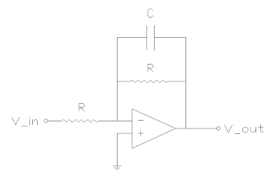
The first circuit is a standard 1 pole active filter. It uses an opamp, a capacitor, and two equal resistors for unity gain. Actually, the gain is -1 (not dB mind you), so it's an inverting amplifier. But we don't care too much about that.
The circuit is a variation on a standard opamp inverter, except now there is a capacitor in parallel with the feedback resistor. So higher frequencies get a lower feedback resistance, which decreases their gain. The equation for the magnitude of the gain in this circuit is as follows.
The cutoff frequency is the same as the passive 1 pole low pass filter.
So we can manipulate the cutoff frequency directly by adjusting R and keeping C constant. The values I chose were
Rtone = 100 Ohms
TonePot = 50KOhms
C = 0.22uF
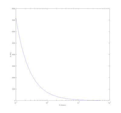
Rtone is put in series with both pots. So R = Rtone + Rtonepot. This gives us a stop at the high end of fc as seen on the graph. The range is 7.2Khz to 14 Hz. 7.2 Khz is very high to listen to alone. I will have to decide whether I like it as a maximum for the circuit. The idea is to crank the tone circuit all the way up and hardly affect the tone at all. So everything under 7.2Khz will be left untouched, and the response will start to drop off after that. But in all seriousness, the pickup itself probably will attenuate those frequencies quite a bit anyway.
**********
Note: This plot is not the correct graph. See Part 3 for a useful graph.
**********
There are two drawbacks to this circuit. Firstly, the frequency change is not linear with change in R. In fact, you'll notice that it is not even linear with changes in log(R). But it doesn't look too terrible with a log tone pot. And hey, we're going from no control to some control, so how upset can we be about nonlinearities. Secondly, it requires a dual-ganged pot. Both resistors much change by the same amount, or the overall magnitude of the gain will change as well. Basically, the inverting amplifier will begin to amplify or attenuate the signal. We only want that to happen when we adjust the volume pot. So there's no way around the problem.
2 Pole Circuit
The second circuit is a Butterworth filter implementation in a Sallen-Key topology. Here is the schematic.
I was pretty happy about the math on this one, so I'll give a little bit more detail. The general gain for the Sallen-Key topology is...
Where Z1 = R1, Z2 = R2, Z3 = 1/(C2s), Z4 = 1/(C1s)
The cutoff frequency and Q factor are given as follows.
We set Q = 1/sqrt(2) to achieve a Butterworth filter. This filter has a maximally flat frequency response prior to the cutoff frequency. Because this is a 2 pole filter, it drops off more steeply than the 1 pole filter described before. With the added steepness, which is desireable in many applications, comes the chance for a non-flat response in the "passband" (prior to the cutoff frequency). The filters tend to have a high peak near the cutoff frequency before dropping off. Designing Q = 1/sqrt(2) makes this peak disappear.
Lets set the resistances equal to each other so that we can use a dual-ganged pot and see what falls out of the equations.
When we plug this back into the Q equation, look what falls out...
That's great! We can totally eliminate the resonate peak around the cutoff frequency by making one capacitor double the other. And this holds true for all values of R, so the filter's response will not change as we adjust the cutoff frequcy. Now, how will that frequency be affected by changing the resistors now that we've come up with the above equations? Substituting in to the fc equation, we get...
That's the exciting part. I hope you're as excited as I am. The equation is almost exactly like the one we had for the 1 pole filter! The factor of sqrt(2) will tend to make our cutoff frequencies a little smaller, but it's a constant factor. Everything remains controllable from a single dual-ganged pot.
Choosing
Rtone = 1 KOhms
Rtonepot = 50 KOhms
C1 = 0.02uF
C2 = 0.01uF
We get the following plot for cutoff frequency.
As you can see, our cutoff frequency on the low end of the R range is higher, and we probably don't go quite as low when we max it out. Actually, for these values the lowest frequency is 220Hz, which is a little high. But different values will yield a better range.
Conclusion
I have shown two circuits with fully adjustable cutoff frequencies. The only drawbacks are the need for a power supply and the dual-ganged pot that will have to be added. For my own purposes, I am back to trying to make a 3-ganged pot. I should be able to do it, since my friend James offered to machine me some parts if I needed them. He's a nice guy.
I will be using the first circuit (1 pole), because it will be more like the original response of the original tone circuit. I realize that I no longer have the ability to flatten out the gain curve, but was that really even that useful? Now I can just move the cutoff frequency down the line and I won't attenuate anything anyway. In my opinion, these are vastly superior circuits. Still, I choose the 1 pole model, because I worry that the 2 pole would drop off too quickly. Plus the 1 pole is slightly easier to source parts for, due to the need for only 1 capacitor. (Yes you can just put two in parallel to get twice the capacitance).
The circuit is finally coming together. I will post the final schematic whenever I get a chance.
Thanks for reading,
Bill
Subscribe to:
Post Comments (Atom)


No comments:
Post a Comment